ESP8266: hardware interface to GSM modules
Connecting any GSM module (SIM900, A6/A7, u-blox, ..) to ESP8266 through serial/UART
ESP8266 is a world phenomenon microcontroller for bringing WiFi connectivity for things (IoT). It's a fully integrated chip with, among other cool things, wireless and UART interfaces.
We can use this microcontroller for sending AT commands to a GSM module.
In hardware terms, it is matter of connecting one of ESP866 UART to the UART of GSM module (while making sure the GSM module you are using is also 3.3V logic-level as the ESP; if it's different, like 5V or 2.8V, you NEED a logic-level converter circuit).
SIMCom modules are all 2.8V logic-level.
Some shields, for example the ones with a SIM900, do contain a logic-level converter that do the conversion from 3.3V.
In this tutorial we will connect it to an A6 module from AiThinker and, as our ESP8266, we will use a Wemos D1 mini.
ESP8266 UARTS
Technically, ESP8266 has two UARTS, 0 and 1. They are available only in specific pins, shown in table bellow:
| GPIO / Wemos pin name | Assignment |
|---|---|
| GPIO1 / TX | UART0 TX also known as TX0 |
| GPIO3 / RX | UART0 RX also known as RX0 |
| GPIO2 / D4 | UART1 TX also known as TX1 |
Notice that UART 1 is transmit only, there is no RX1 pin, only TX1 pin.
Additionally, the API allows you to change UART0 pins assignment to the shown bellow. In LUA/NodeMCU this is done by calling uart.alt(1). In Arduino you call Serial.swap().
| GPIO / Wemos pin name | Assignment |
|---|---|
| GPIO13 / D7 | UART0 RX also known as RX2 |
| GPIO15 / D8 | UART0 TX also known as TX2 |
Connecting A6 GSM module to UART0 on pins GPIO13/GPIO15
We need a dedicated UART to interface with our A6 GSM module, so we MUST use UART0 which has TX and RX.
Problem is, UART0 is also used by Wemos USB connection to you computer to allow you to flash new firmware/program.
So we can't use pins TX0/RX0 as our UART for A6 because it would prevent us to flash any new program. However we can use pins GPIO13 and GPIO15 as our alternative UART for A6, so still allowing us to flash new firmware through USB.
Then, to communicate to A6 with UART0, we must call uart.alt(1) (for NodeMCU, Serial.swap() in Arduino) to toogle its pin assigment to GPIO13 and GPIO15.
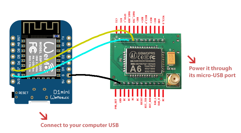
Here are connections that must be done:
| WEMOS D1 | A6 |
|---|---|
| GND | GND |
| D7 / RX2 / GPIO13 | UART_TXD |
| D8 / TX2 / GPIO15 | UART_RXD |
Using UART1 / TX1 for debug output
Now, when you are testing your program, and you switch UART0 to pins GPIO13/GPIO15, it will deactives the USB serial communication to your computer and you won't be able to get helpfull serial output/messages from your program.
What we can do is to use the transmit-only UART1 with its TX1 pin and connect it to a USB <-> Serial converter, so we can print debug messages to UART1 and read them in our computer while at same time using UART0 to communicate with A6 module.
You can use any cheap USB <-> Serial converter with 3V3 logic-level. I recommend CP2102.
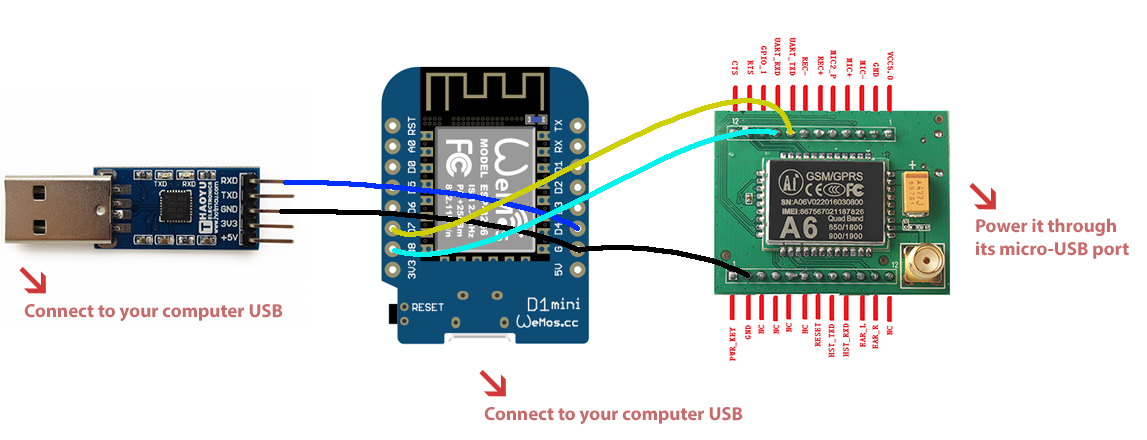
ESP8266 + USB <-> Serial converter connections:
| USB <-> Serial | WEMOS D1 |
|---|---|
| GND | GND |
| RX | D4/IO2/TX1 |
All connections:
To actually test the connection and send AT commands in software, check the next tutorial.